
- Company overview The heart of SMC Vision & Philsophy Partnership Certifications Company culture
- Our service Design and Engineering Maintenance and Service Examine Production Line Upgrade and Transformation Storage and Logistics Processing, Trading and Distributor
- Management Our history Global responsibility Info Center
- Procurement center Internship
- Metal Steel Products Stainless Steel Products Aluminum Products Copper Products Galvanized Steel and PPGI Special Alloy Building Material
- Containers ISO Standard Container Equipment Container Storage Container Tank Container Container Fittings Container Trailer Refrigerated/Reefer Container Offshore Container Container House
- Gas Cylinder & Fire Extinguisher Cryogenic Liquid Cylinder Oxygen Gas Cylinder Storage Tank CNG Gas Cylinder LPG Gas Cylinder Hydrogen Gas Cylinder Nitrogen Gas Cylinder Industry Gas Cylinder Fire Extinguisher
- Metal Machinery Motor Forming Machine Cutting Machine Processing Machine Bending Machine Block Machine Spare Parts Other Machinery
- Mechanical Products Conveyor Belt Miscellany Mooring Equipment Laser Equipment Bearing Marine Equipment Vehicle Industry Pressure Vessel
- Electrical System Transformer Production Line Lighting System Power Distribution Automation Electrical Cable Solar Power System Electric Protection System
- Project Plastic Pipes and Pipe Fittings Fiberglass Reinforced Plastic Pontoon System
Electrolytic Capacitor


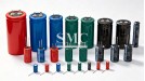
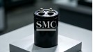
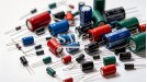
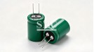
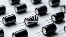
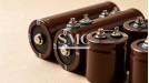
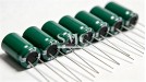
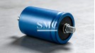
Processing Method: Winding / Laminated assembly
Capacitance Range: 1 μF – 1 F (aluminum electrolytic)
Max Voltage Rating: 6.3 V – 700 V DC
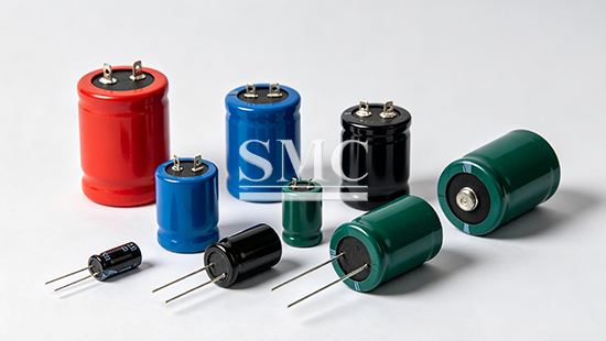
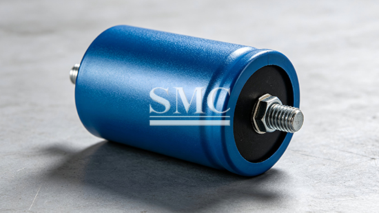
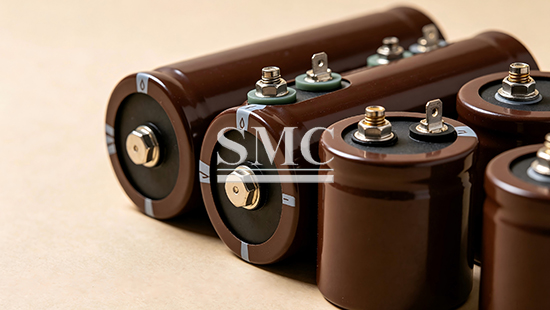
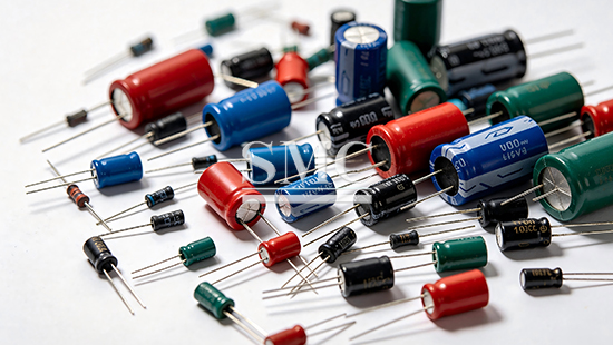
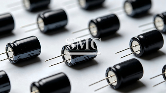
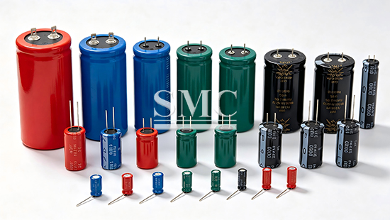
Form Supply: Radial lead / SMD / Screw terminal / Snap-in
Shanghai Metal Corporation is a leading electrolytic capacitor manufacturer and supplier.
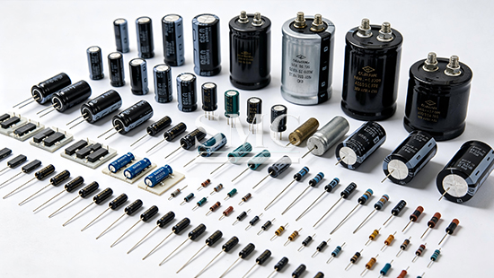
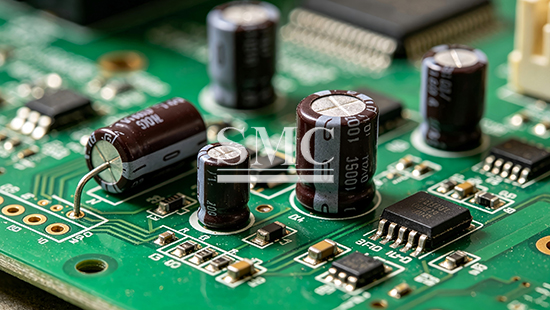
Electrolytic capacitor is a polarized passive component in which the anode is a metal foil (aluminum or tantalum) covered with an insulating oxide layer acting as the dielectric, and the cathode is an electrolyte (liquid or solid) in contact with the oxide layer. It can be configured as aluminum electrolytic, tantalum electrolytic, or solid polymer types to modify ESR, lifetime, and temperature stability. This component can be used for power filtering, energy storage, signal coupling, decoupling, and timing circuits in downstream electronic assemblies. It serves as bulk storage capacitor, ripple smoothing element, and DC-link buffer in power supplies, motor drives, and automotive electronics. Unlike ordinary ceramic or film capacitors, electrolytic capacitors provide extremely high capacitance per unit volume at low cost, but must observe correct polarity and voltage derating. We supply standard catalog parts and can support custom capacitance, voltage, case size, and lead configuration according to customer requirements.
If you want to know more about electrolytic capacitors or other related passive components, please feel free to contact us, we will reply you within 24 hours.



-
1.High Capacitance Density: Provides 1 μF to several farads in a small volume, dozens to hundreds of times higher than ceramic or film capacitors of similar size. It enables compact power supply design and bulk energy storage on limited PCB area.
2.Reliable Ripple Current Handling: Designed to withstand high ripple current in rectifier and switching circuits. Low-ESR grades reduce internal heating and improve efficiency in high-frequency power conversion.
3.Comprehensive Voltage and Temperature Ratings: Available from 6.3 V to 700 V DC and -40℃ to +150℃ depending on series. Stable operation under continuous high-temperature exposure and repeated charge-discharge cycling.
-

-
1.Consumer Electronics Power Supply: Suitable for adapters, chargers, TV, and set-top boxes. Provides filtering and energy storage after rectification. General-purpose and low-ESR grades are commonly used.
2.Industrial and Communication Power: Used in switching power supplies, base stations, and servers. Requires long life and high ripple current capability. Long-life and low-ESR series are recommended.
3.Automotive Electronics: Applied in ECU, infotainment, LED lighting, and motor control. Needs wide temperature range and vibration resistance. Automotive-grade aluminum and tantalum capacitors are selected.
4.Renewable Energy and Motor Drive: Serves as DC-link and smoothing capacitor in inverters, UPS, and wind/solar converters. Screw terminal and snap-in high-voltage series are widely used.
5.Medical and High-reliability Equipment: Used in medical instruments, aerospace, and military electronics. Requires high stability, low leakage, and long life. Tantalum and solid polymer capacitors are preferred for critical circuits.
-

Specification of electrolytic capacitor
|
Item |
Performance Characteristics |
|||||||
|
Operating temperature Range |
=-40 ~+105℃ |
|||||||
|
Rated voltage range |
4~100V |
|||||||
|
Nominal capacitance range |
0.1~1500μF |
|||||||
|
Capacitance tolerance |
±20%(+20℃ ,120Hz) |
|||||||
|
Leakage current |
I ≤ 0.01CRUR or 3(μA), 取较大者(2 分钟)Whichever is greater (at 20℃,after 2 minutes) |
|||||||
|
Dissipation Factor (Max) |
UR(V) |
4 |
6.3 |
10 |
16 |
25 |
35 |
50 |
|
tgδ |
0.35 |
0.28 |
0.24 |
0.2 |
0.16 |
0.14 |
0.12 |
|
|
Load life |
After 1000 hours' application of rated voltage at 105℃ , the capacitor shall meet the following requirement: |
|||||||
|
Capacitance change |
Within ±20% of the initial value( ≤ 16V: within ±25% of the initial value) |
|||||||
|
Dissipation factor |
Not more than 300% of the initial specified value |
|||||||
|
Leakage current |
Not more than the initial specified value |
|||||||
|
Shelf life |
After storage for 1000 hours at 105℃ ,the capacitors shall meet the requirement of load life above. |
|||||||
|
Low Temperature Stability |
UR(V) |
4 |
6.3 |
10 |
16 |
25 |
35 |
50 |
|
Z-25℃ /+20℃ |
7 |
4 |
3 |
2 |
2 |
2 |
2 |
|
|
Z-40℃ /+20℃ |
15 |
8 |
6 |
4 |
4 |
3 |
3 |
|
|
Resistance to Soldering Heat |
The capacitors shall be kept on the hot plate maintained at 250℃ for 30 seconds. After removing from |
|||||||
|
Capacitance change |
Within ±10% of the initial value |
|||||||
|
Dissipation factor |
Not more than the initial specified value |
|||||||
|
Leakage current |
Not more than the initial specified value |
|||||||
|
Item |
Performance Characteristics |
||||||||||||||||||||||||||||||||||||||||
|
Operating temperature Range |
-40~+85℃ |
-25~+85℃ |
|||||||||||||||||||||||||||||||||||||||
|
Rated voltage range |
10~400V |
450~500V |
|||||||||||||||||||||||||||||||||||||||
|
Nominal capacitance range |
68~82000μF |
||||||||||||||||||||||||||||||||||||||||
|
Capacitance tolerance |
±20%(120Hz,+20℃ ) |
||||||||||||||||||||||||||||||||||||||||
|
Leakage Current |
I ≤ 0.01CV 或 1.5mA(5 分钟) 取较小值(after 5 minutes , Whichever is smaller) |
||||||||||||||||||||||||||||||||||||||||
|
Dissipation Factor (+20℃ ,120Hz) |
|
||||||||||||||||||||||||||||||||||||||||
|
Temperature Characteristics (Impedance ratio at 120Hz) |
|
||||||||||||||||||||||||||||||||||||||||
|
Load Life |
After applying rated voltage with specified ripple current for 2000 hours at +85℃ and then resumed 24 hours: Capacitance change : ±20% of the initial measured value Leakage current : ≤ the initial specified value Dissipation factor : ≤ 200% of the initial specified value |
||||||||||||||||||||||||||||||||||||||||
|
Shelf Life |
After storage for 1000 hours at +85℃ , UR to be applied for 30 minutes and then resumed 24 hours: Capacitance change : ±15% of the initial measured value Leakage current : ≤ the initial specified value Dissipation factor : ≤ 150% of the initial specified value |
||||||||||||||||||||||||||||||||||||||||
|
Item |
Performance Characteristics |
|
|
Operating temperature Range |
-40~+85℃ |
-25~+85℃ |
|
Rated voltage range |
10~250V |
350~450V |
|
Nominal capacitance range |
270~820000μF |
|
|
Capacitance tolerance |
±20% |
|
|
Leakage Current |
I ≤ 0.01CV 或 1.5mA(5 分钟) 取较小值(after 5 minutes , Whichever is smaller) |
|
|
Load Life (85℃ ) |
Time : 2000 hours Capacitance change :±20% of the initial measured value Leakage current : ≤the initial specified value Dissipation factor : ≤200% of the initial specified value |
|
|
Shelf Life (85℃ ) |
After test: UR to be applied for 60 minutes, 24 to 48 hours before measurement. Time : 1000 hours Capacitance change : ±20% of the initial measured value Leakage current : ≤the initial specified value Dissipation factor : ≤200% of the initial specified value |
|

Standard Packaging
Each electrolytic capacitor is packed in anti-static bag or tape and reel for SMD types. Radial and snap-in types are arranged in plastic trays or bags with lead protection. Single or multiple parts are separated by shock-absorbing material inside export carton box. Cartons are stacked on fumigated wooden pallets and wrapped by stretch film. Outer package labels mark series, capacitance, voltage, case size, tolerance, batch number, and quantity for product traceability.
Shipping
We support FCL and LCL sea freight, air freight and international express delivery according to total cargo weight, package dimension and destination country. Applicable trade terms contain EXW, FOB, CIF. Other terms may be available upon request. Shipping costs are calculated based on actual gross weight, package outer volume, destination location and selected transport mode.
Lead Time
Samples: 3–7 working days
Standard-spec existing stock orders: 7–15 working days
Custom capacitance, voltage, or special dimension orders: 15–30 working days


Q1: How long does sample preparation take for electrolytic capacitors?
A: If matching standard part is in stock, samples take 3–7 working days. For custom capacitance, voltage, or special case size requiring dedicated production, sample lead-time will extend to 10–20 working days.
Q2: What information do you need for electrolytic capacitor quotation?
A: Please provide capacitance, voltage rating, case size or dimension, mounting type (radial/SMD/snap-in/screw), tolerance, quantity, and special requirements such as low-ESR or long-life. Specify if custom marking or lead forming is needed.
Q3: What is the MOQ and production lead-time?
A: MOQ is 1 reel or 1 box for standard catalog specification. Standard-spec orders take 7–15 working days; custom or special orders take 15–30 working days.
Q4: Can you provide custom capacitance and voltage?
A: Yes, we can support custom capacitance and voltage within our production capability. Minimum order quantity and extra cost depend on the specific rating and case size.
Q5: What is the difference between aluminum and tantalum electrolytic capacitors?
A: Aluminum electrolytic capacitors offer high capacitance and voltage at low cost, suitable for power filtering and energy storage. Tantalum capacitors provide smaller size, stable capacitance, and long life, mainly for high-density and high-reliability circuits.
Q6: What secondary processing can electrolytic capacitors support?
A: They support automatic insertion, wave soldering, reflow soldering (SMD), lead cutting and forming. Excessive reverse voltage or over-voltage shall be avoided to prevent failure, especially for polarized aluminum types.


here
for
price
